The oscillators are electronic circuits makes a respective electronic signal generally the sine wave and the square wave. It is very important in other types of the electronic equipment such as quartz which used as a quartz oscillator. The amplitude modulation radio transmitters use the oscillation to generate the carrier waveform. The AM radio receiver uses the special oscillator it is called as a resonator to tune a station. The oscillators are present in the computers, metal detectors and also in the guns. The different types of oscillators are explained below.
The oscillator works on the principle of the oscillation and it is a mechanical or electronic device. The periodic variation between the two things is based on the changes in the energy. The oscillations are used in the watches, radios, metal detectors and in many other devices use the oscillators.

Oscillator
The oscillator converts the direct current from the power supply to an alternating current and they are used in many of the electronic devices. The signals used in the oscillators are a sine wave and the square wave. The some of the examples are the signals are broadcasted by the radio and television transmitter, clocks which are used in the computers and in the video games.
There are two types of electronic crystal oscillator. They are linear and nonlinear oscillators. The linear oscillators give the sinusoidal input. The linear oscillators consist a mass m and its force in the linear in equilibrium. By applying the hook’s low the spring creates the force that i9s in linear for small displacements.
The different types of oscillators are mentioned below and some of them are explained.
Armstrong Oscillator
Crystal Oscillator
Hartley oscillator
RC Phase Shift Oscillator
Colpitts Oscillators
Cross-Coupled Oscillator
Dynatron Oscillator
Meissner Oscillator
Optoelectronic Oscillator
Phase Shift Oscillator
Wine Bridge Oscillator
Robinson Oscillator
Tri-Tet Oscillator
The Armstrong oscillator is an LC electronic oscillator and to generate this oscillator we are using the inductor and the capacitor. In 912 the US engineer Edwin Armstrong has invented the Armstrong oscillator and it was the first oscillator circuit and also in 1913 this oscillator was used in the first vacuum tube by the Alexander Meissner who as an Austrian engineer.

Armstrong Oscillator
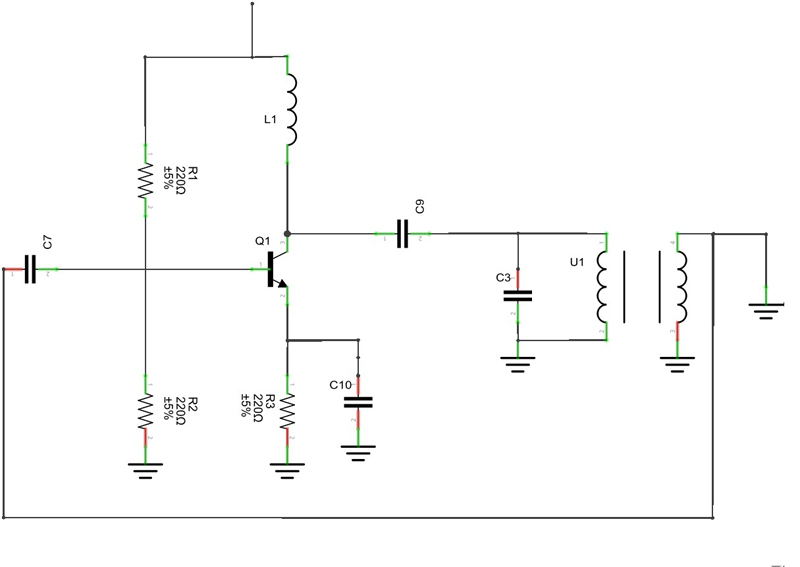
The Armstrong oscillator is known as the tickler oscillator because of the individual features of the feedback signal should produce the oscillations are magnetically coupled to the tank indicator. Let us consider the coupling is weak, but the sustain oscillation is sufficient. The following equation shows the oscillation frequency f. The Armstrong oscillator is also called as the Meissner oscillator or tickler oscillator.
f = 1 / 2Π√LC
To achieve the 180-degree phase shift oscillation, the Armstrong oscillation uses the transistor, which is shown in the above figure. From the figure, we can observe that the output is from the primary transformer it has a transistor and the feedback is taken from the secondary coil of the transformer. By seeing the polarity dots in the transformer secondary coil is inverted using the primary coil. The operating frequency is obtained by the capacitor C1 and the primary of the transformer.
The Hartley oscillator is an electronic oscillator. The frequency of this oscillation is determined by the tuned circuit. The tuned circuit consists of the capacitor and inductor, hence it is an LC oscillator. In 1915 by American engineer Ralph Hartley has invented this oscillator. The features of the Hartley circuit are the tuned circuit consists of a single capacitor in parallel with the two inductors which are in series. From the center connection of the two inductors for oscillation purpose, the feedback signal is taken. Follow the below link to know more about Hartley Oscillator Circuit and Its Working

Hartley Oscillator
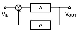
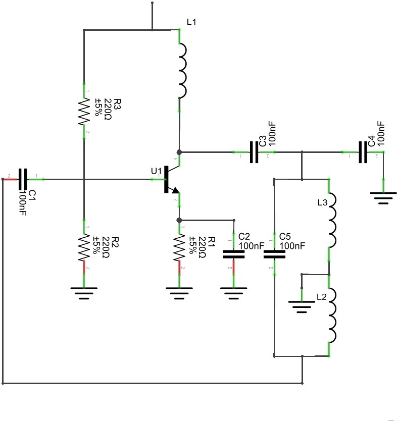
The Hartley oscillator is parallel to the Colpitts apart from that it uses a pair of tapping coils as an alternate of two tapped capacitors. From the below circuit the output voltage is developed across the inductor L1 and the feedback voltages are across the inductor L2. The feedback network is given in the mathematical expression which is given below
Feedback network = XL2 / XL1 = L 2 / L 1
Applications
This oscillation will produce a desired range of frequencies
The Hartley oscillators are used in the radio frequency in a range of the 30Mhz
In radio receiver, this oscillator is used and it has a wide range of frequency
The Colpitts Oscillator was by American engineering by Edwin H. Colpitts in the year of 1918. This oscillator is a combination of both inductors and capacitor. The features of the Colpitts Oscillator are the feedback for the active devices and they are taken from the voltage divider and made up of two capacitors which are in series across the inductor. Follow the below link to know more about Collpits Oscillator Working and Its Applications

Colpitts Oscillator
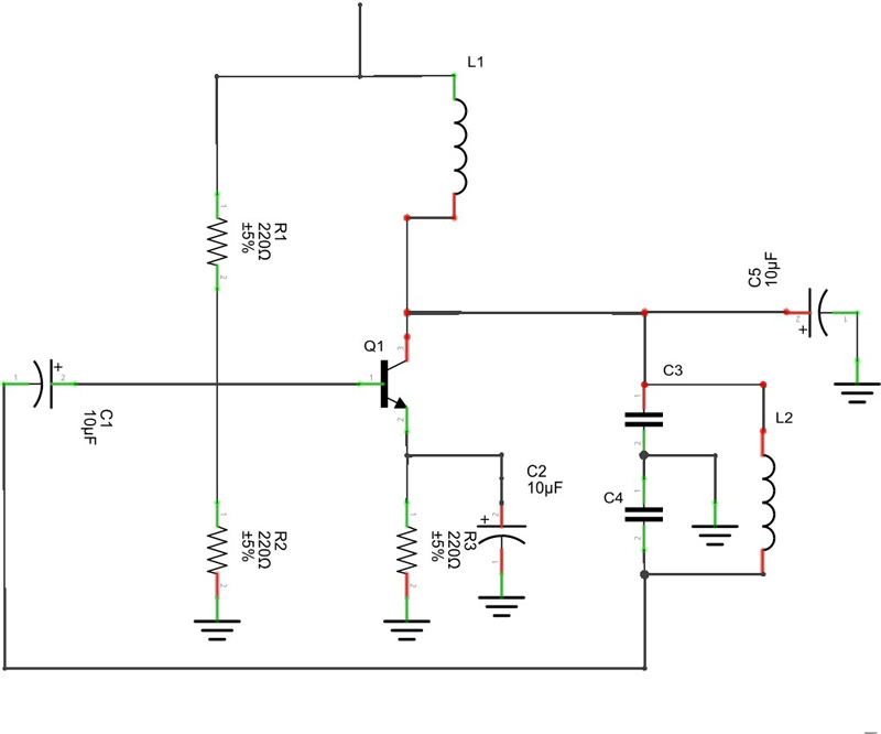
The Colpitts circuits consist of gain devices such as the bipolar junction, field effect transistor, operational amplifier and vacuum tubes. The output is connected to an input in a feedback loop it has a parallel tuned circuit and it functioned as a band-pass filter is used as a frequency of the oscillator. This oscillator is an electrically dual of the Hartley oscillator hence the feedback signal is taken from the inductive voltage divider it has two coils in the series.
The following circuit diagram shows the common base Colpitts circuit. The inductor L and the both the capacitors C1 & C2 are in series with the parallel resonant tank circuit and it gives the frequency of the oscillator. The voltage across the C2 terminal is applied to the base-emitter junction of the transistor to create the feedback oscillations.
Applications
It is used to generate the sinusoidal output signals with a very high frequency
Very wide range of frequencies is involved
It is used in the radio and mobile communications
In commercial purpose, many applications are used
The multi-wave oscillator was invented by the French engineer by Georges Lakhovsky in the year of 1920 to 1940. He showed that the nucleus of the cell with the filaments stands, it is very similar to the electronic oscillator and it has the capability of receiving & sending the vibratory information. The multi-wave oscillators are experimental, research for the historical instrument, and there is a no medical claim is made. The multi-wave oscillator unit presents the printed circuit board Golden ratio antenna.
Applications
The healing action of this oscillation is very bad because of the holistically work
The healing process is done by all parts of the body
The MWO is used in many countries worldwide by individual
This oscillator is applied for the treatment of the cancer
(Resource:https://www.elprocus.com/different-types-of-oscillator-circuits-its-applications/)